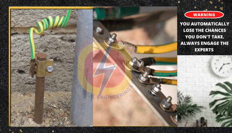
Home / Blog Posts / Earthing System in Electrical Wiring
Earthing System in Electrical Wiring
Unlock the Secrets of Earthing Systems in Electrical Wiring!
Discover how TN-S, TN-C, TN-C-S, TT and IT systems work. In a TN-S system, neutral (N) and protective earth (PE) conductors remain separate throughout.
• Learn about grounding at a single point
• Understand electrical installation essentials
Watch a Video on Earthing System In Electrical Wiring
What is earthing System in electrical wiring?
Earthing, also known as grounding in electrical wiring systems, is the process of connecting an electrical circuit or system to the earth, typically through a physical connection to the ground. This connection provides a safe path for electrical currents to flow to the ground, reducing the risk of electrical shock, injury, or death.
In an Electrical wiring, what is the purpose for an earthing System?
Earthing serves several purposes in electrical wiring system:
- Safety: Earthing provides a safe path for electrical currents to flow to the ground, reducing the risk of electrical shock or electrocution.
- Protection: Earthing protects electrical equipment and appliances from damage caused by lightning strikes, power surges, or other electrical faults.
- Stability: Earthing helps to stabilize electrical systems by providing a reference point for voltage and current.
- Noise reduction: Earthing can help reduce electromagnetic interference (EMI) and radio-frequency interference (RFI) in electrical systems.
In an Electrical wiring, how many methods of earthing systems are there?
Earthing systems typically consist of:
- Earthing electrodes: These are physical connections to the ground, such as rods, plates, or grids.
- Earthing conductors: These are wires or cables that connect the earthing electrodes to the electrical system.
- Earthing connections: These are the physical connections between the earthing conductors and the electrical system.
These are some of the different types of earthing systems in electrical wiring:
- TN-S earthing: A system where the neutral conductor is connected to the earth at the source.
- TN-C-S earthing: A system where the neutral conductor is connected to the earth at the source and at the consumer’s premises.
- TT earthing: A system where the earth connection is provided separately from the neutral conductor, Etc.
Earthing is an essential aspect of electrical safety and is required by many electrical codes and standards, including the National Electric Code (NEC) and the International Electrotechnical Commission (IEC) standards.
Brief explanation of Earthing System Terms: TN-S, TN-C, TN-C-S, TT and IT
TN-S means Terre-Neutre-Separate
- In TN-S, the neutral (N) and protective earth (PE) conductors are kept separate throughout the entire electrical installation. The neutral is grounded at a single point.
TN-C means Terre-Neutre-Combined
- In TN-C, the neutral and protective earth functions are combined into a single conductor for part of the installation. However, they are separated as they approach the user’s equipment.
TN-C-S means Terre-Neutre-Combined-Separate
- TN-C-S is a hybrid system that combines TN-C and TN-S. It has a combined neutral and protective earth conductor in some parts, and in others, they remain separate.
TT means Terre-Terre
- In a TT system, each item of electrical equipment is connected to the ground independently. The earth connection is not dependent on the supply system and is established locally for each device.
IT means Isolated Terre
- In an IT system, the neutral of the power supply is connected to the ground, but the individual pieces of electrical equipment are isolated from the ground.
“Terre” is the French word for “earth” or “ground.” In the context of electrical systems and earthing, “terre” refers to the grounding or earthing of electrical installations. Grounding is a safety measure that connects electrical systems to the Earth’s conductive surface to prevent electric shocks and ensure the safe dissipation of fault currents. The term is commonly used in the description of different types of earthing systems
“Neutre” in French translates to “Neutral” in English:
In the context of electrical systems, especially in earthing systems like TN-S, TN-C, TN-C-S, TT, and IT
Examples,
- In the above, TN-S (Terre-Neutre-Separate) the same as (Earth-Neutral-Separate)
- In the above, TN-C (Terre-Neutre-Combined) the same as (Earth-Neutral-Combined)
- In the above, TN-C-S (Terre-Neutre-Combined-Separate) the same as (Terre-Neutre-Combined-Separate)
- In the above, TT (Terre-Terre) the same as (Earth-Earth)
- In the above, IT (Isolated Terre) the same as (Isolated Earth).
How does Earthing work in Electrical Wiring?
Earthing, also called grounding, is a safety system that protects people and equipment from electric shock. Earthing in electrical wiring works by giving fault current a path to the ground, stopping dangerous voltage from building up on exposed metal parts.
During normal operation, electricity flows from the live wire into your device, then returns to the transformer through the neutral wire. The earth wire does nothing in this state and therefore the earth wire stays at zero volts and carries no current.
But if something goes wrong (like a live wire breaking and touching the metal body of an appliance) the fault current needs a way to escape. That is when the earth wire steps in. It gives the current a direct path to the ground or back to the transformer, depending on the setup.
Because this path has low resistance, a large amount of current flows quickly. That sudden surge is what trips a circuit breaker or activates the RCD. Power cuts off immediately, preventing electric shock and reducing the risk of fire.
What is the purpose of Earthing in electrical wiring?
The main purpose of earthing in electrical wiring is to keep you and your property safe. When a fault happens (like a live wire touching metal) earthing directs that current away from your body or the metal case. It also helps breakers or fuses trip quickly by allowing high fault current to flow into breaker and fuses. In normal use when there is no fault or current leakage, the earth wire stays at zero volts and carries no current. But when there is fault or leakage in the electrical wiring, the earthing system becomes the safety net.
What are Components of an Earthing System in electrical wiring?
A basic earthing system in electrical wiring has a few important components that work together to protect you. First is the earth electrode. This is usually a metal rod or plate buried in the ground. It connects the electrical wiring system to the soil which allows fault current to flow into the earth if something goes wrong.
Next is the earth wire. It connects the metal parts of appliances (like the outer casing of a washing machine) to the earth electrode. If a live wire touches the metal case, the earth wire carries the fault current safely away. All the earth wires in a building connect at one point called the main earthing terminal. This is the hub where everything comes together. Inside cables, there’s another earth wire called the circuit protective conductor. It runs alongside the live and neutral wires and adds extra safety by giving fault current a quick path to ground.
Finally, residual current devices (RCDs) keep watch. They constantly check for current leaks. If they detect any difference between the live and neutral current (meaning some current is escaping) they cut the power immediately. This helps prevent shocks and fires.
Together, these parts make sure that if a fault happens, the current flows through the earth system instead of through you or metal case of your appliances.
Why is Earthing in electrical wiring Essential
Proper earthing makes sure faults don’t turn appliances into shock hazards. It ensures that protective devices act fast and helps reduce electrical noise in sensitive gear. Without it, fault current might energize metal parts, leading to shocks or fires.
How does electric current flow through the earthing system and return to the power supply source via the ground?
Normal Operation
In a healthy electrical system, current flows from the power source through the live wire, powers the load, and returns through the neutral wire to complete the circuit. The grounding or earthing system stays inactive during normal operation, with no current flowing through the earth.
Fault Condition (Line-to-Ground Short)
But if a fault occurs (like a live wire touching a grounded metal part) the current tries to return to the source through any available path. In TN and TT systems, the neutral is bonded to earth at the transformer or service panel, so fault current flows through the earth electrode and soil to the transformer’s neutral point, and also through the equipment grounding conductor, which offers a lower-resistance path.
Earth or soil as a Conductor
Soil has higher resistance than metal, but still allows enough current to flow to trip breakers or ground fault devices. In TT systems, the earth is the only return path, so they use residual current devices (RCDs) for protection. The neutral-to-earth bond at the transformer or generator which gives the system a stable voltage reference creates a defined path for fault current to return and ensures protective devices trip quickly. Without this bond, voltages can drift and faults might not be detected.
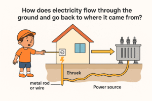
If earth (soil) isn’t a good conductor, how does current flow through it back to the transformer?
The answer is simple: the truth is, the earth does not carry current like a wire. It works as a backup path during faults, not as part of the normal circuit.
Let me explain in simple parts:
Normal current doesn’t flow through the earth
In a normal system, current flows from the transformer through the live wire, powers your devices, then returns through the neutral wire. No current flows through the earth during regular operation.
The earth is a safety backup
The earth rod comes into play only when something goes wrong, like a short circuit, a broken neutral, or a live wire touching a metal case. In those cases, the earth rod provides a low-resistance path for fault current. Even though soil has high resistance, it still allows enough current flow because of moisture, salts and minerals.
How does current reach the transformer if the earth is poor conductor?
The earth or ground is truly poor conductor but when fault current enters the earth rod, it spreads out through the soil. Eventually, it reaches other buried metal parts, including the transformer’s own grounding system. This completes the path, letting the current return to the source through the transformer’s neutral. The resistance is high, but fault currents are large, so the voltage difference is enough to push current through.
Real-life example:
In real life, if a live wire touches a metal appliance and you’re barefoot, your body could become the path to ground. That’s dangerous! But if there is an earth rod, the current flows into the rod instead, through the ground and back to the transformer which then trips the breaker and cut the power supply to the faulty circuit.
The takeaway: soil is not a great conductor, but it’s good enough for protection during faults. The earth rod doesn’t replace wires. It’s a safety net, not part of the main circuit. The true return path for current is still the neutral wire.
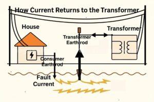
By understanding how current flows through the earth, we can design more effective earthing systems that provide reliable protection against electrical faults.
You can only treat the soil around the earth rod and the transformer, what happens to the soil that is many miles between the earth rod the supply transformer
You’re right; treating the soil around the earth rod and transformer won’t affect the vast amount of soil in between. However, the key point is that the earth doesn’t need to be a perfect conductor for the earthing system to work.
How does Earthing System in Electrical Wiring Works Over Long Distances
- Earthing system in electrical wiring works over long distances like this: when a fault occurs, the current flows through the earth rod and into the earth, creating a potential gradient around the rod.
- The current flows through the earth in the vicinity of the earth rod, rather than flowing directly through the earth to the transformer miles away.
- The transformer also has its own earthing system, which provides a path for fault currents to flow back to the transformer.
Role of the Earth or Soil in Earthing System Electrical Wiring
The earth or soil in earthing system in electrical wiring serves as a common reference point for the earthing system, allowing fault currents to flow and enabling protective devices to operate. While the earth isn’t a perfect conductor, it’s sufficient for the earthing system to function.
Design Considerations
Earthing system design takes into account the soil resistivity and other factors to ensure effective operation. This includes:
- Earth electrode design: The design of the earth electrode, including its material, size, and depth, is critical for effective earthing.
- System design: The overall earthing system design, including the connection to the transformer and other equipment, is crucial for ensuring safety and reliability.
By understanding how earthing works, we can design systems that provide reliable protection against electrical faults, even over long distances.
Testing of Earthing Systems in electrical wiring
Electricians use specific tests to make sure the earthing system is working correctly.
The earth electrode resistance test measures how well the buried rod or plate connects to the surrounding soil. Lower resistance means better fault current flow. The earth fault loop impedance test checks if enough current can flow during a fault to trigger breakers or fuses. RCD tests verify that these devices shut off power fast when they detect a current leak.
Earthing doesn’t carry current under normal conditions. But when a fault happens, it’s what saves lives. It redirects dangerous current away from people and into the ground. Without proper earthing, even a small fault can lead to electric shock, fire, or equipment damage.
Electrical Earthing Test Procedure
Purpose:
To verify the effectiveness and resistance of the earthing system in accordance with safety standards, ensuring proper fault current dissipation and personnel protection.
Tools & Equipment Required:
Earth Resistance Tester (3-point or 4-point method – e.g. Megger or similar)
Earth test leads and metal spikes (electrodes)
Measuring tape
Hammer (to drive the spikes)
Personal Protective Equipment (PPE)
Logbook or checklist
Safety Precautions:
Ensure the system is de-energised (if applicable).
Use PPE: safety boots, gloves, and eye protection.
Keep the test area clear and dry.
Follow lockout-tagout (LOTO) procedures if working in high-risk zones.
Test Method: Fall-of-Potential (3-Point Method)
(Standard and widely used for earth electrode testing)
Step-by-Step Procedure:
1. Disconnect the Earth Electrode
Isolate the earth electrode under test from the system (if testing an individual rod) to avoid parallel paths.
2. Place the Electrodes
Drive the current electrode (C2) about 30-50 metres away from the test electrode.
Drive the potential electrode (P2) about 15-25 metres away, midway between the test rod and the current spike.
Use a measuring tape for accurate placement.
3. Connections to the Tester
Connect the test electrode (E) to the ‘Earth’ terminal of the tester.
Connect the potential electrode (P2) to the ‘Voltage (V)’ terminal.
Connect the current electrode (C2) to the ‘Current (I)’ terminal.
4. Power On the Tester
Turn on the earth tester and initiate the test. The tester will send a small current through the earth and measure the voltage drop to calculate resistance.
5. Record the Earth Resistance
Note the resistance value in ohms (Ω).
Acceptable values depend on the application:
In General earthing: <5 ohms
For Sensitive equipment: <1 ohm
Lightning protection: <10 ohms
6. Confirm Stability
Move the potential electrode 5m forward and back from its midpoint and repeat the test.
If resistance values are consistent (within ±10%), the result is valid.
If they vary significantly, increase the spacing or improve soil contact and repeat.
If the measured earth resistance is too high (i.e., above acceptable limits like 5 ohms or 1 ohm depending on the application), you must take steps to improve the earthing system
Steps to Improve High Earth Resistance Values
Add More Earth Electrodes
1. Add More Earth Electrodes
Install additional earth rods (vertical or horizontal) and connect them together with copper conductors.
Drive rods at least 2 metres apart to reduce mutual resistance.
Interconnect them in a parallel configuration to effectively lower the total resistance.
Adding more rods lowers resistance due to multiple paths for current flow.
2. Drive Earth Rods Deeper
Extend the depth of the earth rod if possible.
The deeper you go, the lower the soil resistivity, especially in dry seasons or rocky areas.
Moist soil at deeper levels conducts better than dry surface layers.
3. Use Conductive Earthing Enhancers
Add earth enhancement compounds like:
Bentonite clay
Marconite
Ground enhancement gels
Charcoal + salt (traditional but temporary)
These materials reduce soil resistivity around the rod and maintain stable contact over time.
These are especially helpful in rocky, dry, or sandy soils.
4. Increase the Surface Area in Contact with Soil
Replace single rods with earth plates or earth meshes buried horizontally.
Increase contact area by using copper tapes or large diameter rods.
More surface contact means better dissipation of fault currents.
5. Improve Soil Moisture and Compaction
Pour water regularly around the earth pit (temporary solution).
Add salt and charcoal around the rod to maintain moisture (if allowed).
Avoid loose, dry soil – compact the earth after installation.
Moist soil drastically reduces earth resistance.
6. Check and Clean All Connections
Ensure all earth rods, clamps, and connectors are tight, rust-free, and corrosion-resistant.
Use brass or copper connectors, and apply anti-oxidation paste if needed.
Loose or corroded connections can falsely raise test values.
Earthing System In Electrical Wiring:
If you have any questions prior to this topic, feel free to visit the Faq (Frequently asked questions) page and ask a question. You can visit the Blog Posts page to read other topics
Always Hire a Professionals
No matter urgent any electrical repairs seem, it’s never okay to attempt to handle them on your own. Trying to take care of electrical problems without professional training is extremely dangerous. If you or someone else aren’t hurt during your attempt, there’s still a chance that you’ve left something undone that poses a huge risk to you, your home, or your family

Electrical Wiring in Accra – Ghana
Our electrical wiring technicians know what a hassle any electrical problems can be, which is why we’ll always respond to any requests for service as quickly as possible. And because all of our technicians are licensed, background checked, and professionally trained, you’re guaranteed to receive the best quality service and workmanship available when you call us. We can assist with all your electric needs including:
- Generator Installation and Repair Services
- Best Industrial Electrical Automation services
- Best Electric Motor Rewinding Services
- Earthing Installations and Upgrades Services
- Electro-Mechanical services
- Lighting Installation
- Residential Electrical Installation Services
- Electrical Panel Replacement
- LED Lighting
- Industrial electrical Installation Services
- Electrical Troubleshooting and Repairs
- Professional Electrical Support and Training Services
- Electrical Wiring Design and Engineering Services
- Electrical Energy and Power Auditing Services
- Distribution Panels Fabrication and Upgrades Services
- Professional electrical contractors in Ghana
- Commercial electrical Installation Services
- Licensed Electricians in Ghana
- Home Wiring
- Consulting and Advisory services
- Electrical Wirings Testing and Inspection Services
- Wiring Replacement and Upgrade Services
- Residencial, commercial and Industrial wiring Services
When searching for a reliable electrician, call us at +233 24 415 1232 We specialize in electrical repairs, indoor and outdoor lighting installations, panel upgrades, and even hot tub wiring!
Search
Electrical Wiring Contract – What Can Go Wrong or Right
Generator Service Experts in Ghana, When the Lights Go Out – Mega Solution Electrical to the Rescue!
Categories
- Certified Electricians Ghana
- Commercial Electrical Services
- Commercial Installation
- Consulting Services
- Contracting Services
- Control Systems
- Distribution Panel Fabrication
- Earthing Installations
- Earthing Maintenance
- Electrical Consulting
- Electrical Contractors
- Electrical Installation Ghana
- Electrical Maintenance Ghana
- Electrical Repair Ghana
- Electrical Safety
- Electrical Services
- Electrical Training
- Energy Auditing
- Engineering Services
- Generator Installation
- Generator Load Testing
- Generator Repair
- Generator Services
- Generator Servicing Ghana
- Ghana Electrical Licensing
- Ghana Electrical Services
- Industrial Electrical Services
- Industrial Installation
- Industrial Services
- Industrial Solutions
- Installation Services
- Licensed Electricians
- Motor Rewinding
- Residencial Installation
- Residential Electrical Service
- Residential Services
- Uncategorized
Archive
| M | T | W | T | F | S | S |
|---|---|---|---|---|---|---|
| 1 | 2 | 3 | 4 | |||
| 5 | 6 | 7 | 8 | 9 | 10 | 11 |
| 12 | 13 | 14 | 15 | 16 | 17 | 18 |
| 19 | 20 | 21 | 22 | 23 | 24 | 25 |
| 26 | 27 | 28 | 29 | 30 | 31 | |
Tags
- Commercial Electrical Contracting
- Commercial Electrical Installation Ghana
- Commercial Electrical Repair
- Commercial Electrical Wiring
- Commercial generator maintenance
- Earthing Installations and Upgrades Services
- Electrical
- Electrical Automation Services
- Electrical CAD Design
- Electrical Company
- Electrical Contractors in Ghana
- Electrical Energy and Power Auditing Services
- Electrical Wiring Design and Engineering Services
- Electrical Wiring Design Ghana
- Electrical Wiring Upgrades
- Electricians
- Electricians in Ghana
- Electric Motor Repair
- Electric Motor Rewinding
- Electric Motor Rewinding Services
- Factory Electrical Installation
- Generator experts in Ghana
- Generator installation
- Generator Installation and Repair Services
- Generator Installation Ghana
- Generator Maintenance Contracts
- Generator Repairs
- Generator Repair Services
- Generator Repair Services Ghana
- Generators
- Industrial Electrical Contracting
- Industrial Electrical Installation Ghana
- Industrial Electrical Maintenance
- industrial Electrical Repair
- Industrial Electrical Wiring
- Industrial generator repair services
- Installations
- Licensed Electrical Contractors Ghana
- Licensed Electricians in Ghana
- Residential Electrical Installation Ghana
- Residential Electrical Maintenance
- Residential Electrical Repair
- Residential Electrical Wiring
- Residential standby generator repair
- Wiring Installation Design
Prayer Warfare


