

Home / Blog Posts / Earthing and Lightning Protection: Keep Your Property Safe
14 Jul, 2026
Posted by Mega Solution Electrical Engineering Ltd
0 comment
Earthing and Lightning Protection: Keep Your Property Safe
Earthing and lightning protection are not optional safety measures. They are fundamental engineering requirements. Every electrical installation depends on them to protect human life, preserve equipment, ensure regulatory compliance, and maintain system integrity. A property without correct earthing and lightning protection exposes every person inside to electrocution risk. It subjects every connected piece of equipment to damage from fault currents and lightning surges. Furthermore it creates legal liability for the property owner when things go wrong. This complete guide to earthing and lightning protection covers every aspect of system design, component selection, installation requirements, and testing procedures. It applies to residential, commercial, and industrial applications worldwide and references every applicable international standard.
Earthing and Lightning Protection: The Complete Installation and Safety Guide for Homes, Businesses, and Industrial Facilities
What Is Earthing and Why Does It Matter
Earthing, also called grounding in North American terminology, is the deliberate electrical connection of all exposed metallic parts of an electrical installation to the general mass of earth. This connection provides a low resistance path for fault currents to flow safely to earth, enabling protective devices including circuit breakers and residual current devices to operate correctly and clear faults rapidly.
Without correct earthing a fault current that reaches an exposed metallic surface such as the casing of an appliance or a metal distribution board has nowhere to flow. The fault voltage remains present on the metallic surface. Any person who touches that surface while in contact with earth becomes the fault current path. The resulting electric shock can be fatal.
How Earthing Protects People and Equipment
Earthing provides protection through three distinct mechanisms that work simultaneously in every correctly designed electrical installation.
Fault current clearance is the primary protection mechanism. When an insulation fault allows live voltage to reach an exposed conductive part the earthing system provides a low impedance path for the fault current. That current activates the upstream overcurrent protection device, clearing the fault rapidly. It removes the dangerous voltage from the exposed surface. The lower the earthing system impedance the higher the fault current and the faster the protective device operates.
Equipotential bonding eliminates dangerous voltage differences between simultaneously accessible conductive parts. In a bathroom a person touching both a bath tap and an electric heater casing risks electric shock if a voltage difference exists between those two surfaces. Bonding connects all simultaneously accessible conductive parts to the same earth potential. This eliminates the voltage difference regardless of any fault condition.
Surge voltage limitation protects electronic equipment from transient overvoltages. Lightning strikes, switching operations, and power system disturbances generate these overvoltages. A correctly designed earthing system provides the low impedance reference point that surge protection devices require. Without it transient currents cannot divert safely to earth without damaging connected equipment.
The Consequences of Inadequate Earthing
Inadequate earthing causes consequences that range from nuisance equipment malfunctions to fatal electrocution. Understanding these consequences establishes the true cost of earthing system neglect.
Electric shock fatalities occur when fault voltage reaches accessible metallic surfaces in an installation with inadequate earthing. IEC 60479 specifies human body impedance values that vary with contact voltage, skin condition, and current path. A representative body resistance of approximately 1,000 ohms applies under normal dry skin conditions. At this resistance a 230 volt fault on an unearthed metal surface drives approximately 230 milliamperes through a person in contact with earth. IEC 60479 establishes that currents above approximately 30 milliamperes through the heart region can cause ventricular fibrillation. At 230 milliamperes the outcome is fatal within seconds.
Equipment damage from fault currents occurs when the earthing system cannot provide adequate fault current. Without adequate fault current protective devices cannot operate within their required clearing time. Sustained fault currents below the protective device trip threshold cause progressive thermal damage to cables, insulation, and connected equipment without triggering protective disconnection.
Electromagnetic interference affects sensitive electronic equipment in installations with inadequate earthing. Variable speed drives, programmable logic controllers, communications equipment, and medical devices all require a low impedance earth reference. Without it electromagnetic compatibility performance degrades significantly. Poor earthing causes interference that corrupts data, triggers spurious alarms, and causes unpredictable equipment behaviour.
Regulatory non-compliance exposes property owners and electrical contractors to legal liability. IEC 60364, BS 7671, the Ghana Wiring Regulations, and every other national electrical installation standard mandates specific earthing requirements. A property without compliant earthing cannot receive a valid electrical installation certificate. Additionally it exposes its owner to insurance liability in the event of any incident.
Earthing System Types: TN, TT, and IT
International standards define three fundamental earthing system types. Each determines how the supply transformer neutral and installation exposed conductive parts connect to earth. Selecting the correct earthing system type for each application is fundamental to correct protection design.
TN Earthing Systems
The TN earthing system connects the supply transformer neutral directly to earth at the transformer. It then connects all installation exposed conductive parts to that neutral through the protective conductor. TN systems have three variants.
TN-S uses separate neutral and protective conductors throughout the installation. TN-C combines the neutral and protective functions in a single PEN conductor throughout. TN-C-S uses a combined PEN conductor from the transformer to the installation origin, then separates into individual neutral and protective conductors within the installation. TN systems provide low earth fault loop impedance that enables reliable overcurrent protection device operation.
An important restriction applies to TN-C wiring. IEC 60364 prohibits TN-C wiring in installations with socket outlets rated below 32 amperes. It also prohibits TN-C in flexible cables and in locations where the PEN conductor risk breaking. A broken PEN conductor in a TN-C system places full supply voltage on all exposed conductive parts connected to it, creating an extremely dangerous condition. Engineers specifying earthing systems must apply this prohibition rigorously.
TT and IT Earthing Systems
The TT earthing system connects the supply transformer neutral to earth at the transformer. However it connects installation exposed conductive parts to a separate independent earth electrode at the installation rather than to the transformer earth. Engineers commonly specify TT systems in rural areas where the supply network does not provide a metallic return path for fault current. Additionally TT systems require residual current devices for personal protection. The earth fault loop impedance through two separate earth electrodes is too high for reliable overcurrent protection operation alone.
The IT earthing system isolates the supply from earth entirely or connects it through a high impedance. Engineers and facility managers use IT systems in locations where supply continuity is critical including operating theatres, mines, and some industrial process applications. A first earth fault in an IT system does not cause dangerous touch voltage. Furthermore it does not interrupt the supply, allowing operations to continue while engineers locate and repair the fault.
Earthing System Components and Installation
A correctly installed earthing system consists of several interconnected components that together provide the low impedance earth connection required for safe and compliant electrical installation operation.
Earth Electrodes and Grounding Rods
Inadequate earthing causes consequences that range from nuisance equipment malfunctions to fatal electrocution. Understanding these consequences establishes the true cost of earthing system neglect.
Electric shock fatalities occur when fault voltage reaches accessible metallic surfaces in an installation with inadequate earthing. IEC 60479 specifies human body impedance values that vary with contact voltage, skin condition, and current path. A representative body resistance of approximately 1,000 ohms applies under normal dry skin conditions. At this resistance a 230 volt fault on an unearthed metal surface drives approximately 230 milliamperes through a person in contact with earth. IEC 60479 establishes that currents above approximately 30 milliamperes through the heart region can cause ventricular fibrillation. At 230 milliamperes the outcome is fatal within seconds.
Equipment damage from fault currents occurs when the earthing system cannot provide adequate fault current. Without adequate fault current protective devices cannot operate within their required clearing time. Sustained fault currents below the protective device trip threshold cause progressive thermal damage to cables, insulation, and connected equipment without triggering protective disconnection.
Electromagnetic interference affects sensitive electronic equipment in installations with inadequate earthing. Variable speed drives, programmable logic controllers, communications equipment, and medical devices all require a low impedance earth reference. Without it electromagnetic compatibility performance degrades significantly. Poor earthing causes interference that corrupts data, triggers spurious alarms, and causes unpredictable equipment behaviour.
Regulatory non-compliance exposes property owners and electrical contractors to legal liability. IEC 60364, BS 7671, the Ghana Wiring Regulations, and every other national electrical installation standard mandates specific earthing requirements. A property without compliant earthing cannot receive a valid electrical installation certificate. Additionally it exposes its owner to insurance liability in the event of any incident.
Earthing Conductors and Bonding
The earth electrode makes electrical contact with the general mass of earth. It is the conductive element buried in the ground that completes the earthing system. Several electrode types suit different soil conditions and installation requirements.
Vertical driven rods are the most commonly used earth electrode type globally. Engineers and electricians install copper clad steel rods typically 1.2 to 2.4 metres long and 14 to 16 millimetres in diameter. They drive them vertically into the ground using a driving tool. Where a single rod does not achieve the required earth resistance engineers drive additional rods and connect them in parallel. Maintain minimum spacing between parallel rods equal to twice the rod length. This prevents resistance zones of adjacent rods from overlapping and reducing the effectiveness of each additional rod.
Horizontal buried conductors, also called earth mats or ring electrodes, consist of bare copper conductors. Engineers bury them horizontally at a depth of 0.5 to 1.0 metres. They are particularly effective in two situations. Rocky ground prevents engineers from driving vertical rods to adequate depth. Large industrial installations benefit from a low resistance earth mat beneath the facility that provides both earthing and step and touch voltage control.
Plate electrodes consist of copper or galvanised steel plates buried vertically in the ground. They suit locations with shallow soil above rock where horizontal conductors and vertical rods cannot achieve adequate burial depth.
Foundation electrodes, also called concrete encased electrodes or Ufer grounds, use building foundation reinforcing steel as the earth electrode. Moisture retained in concrete maintains good electrical contact with surrounding soil throughout the year. This provides a stable low resistance earth connection that benefits from the large surface area of the foundation structure.
Main Earthing Terminals and Earth Bars
The main earthing terminal is the central connection point within the installation. Also called the main earth bar or earthing busbar, it connects all protective conductors, bonding conductors, and the earthing conductor to the earth electrode together.
IEC 60364 Part 5-54 requires engineers and electricians to keep the main earthing terminal accessible for testing and inspection. It must incorporate a removable link. Engineers use this link to break the connection between the installation earthing system and the earth electrode for earth resistance measurement. Breaking this link does not disconnect individual protective conductors from their circuits.
Large installations use earth bar systems that distribute the earth connection to multiple distribution boards and equipment locations throughout the facility. Engineers size earth bars to carry the maximum earth fault current without overheating. They label earth bars clearly to identify them as safety earthing components. Unauthorised personnel must not modify or remove them without proper engineering authorisation.
Equipotential Bonding
Equipotential bonding connects all simultaneously accessible conductive parts within a location to the same earth potential. This eliminates dangerous voltage differences that could cause electric shock even in the absence of an electrical fault.
Main equipotential bonding connects all metallic services entering the building to the main earthing terminal. These services include water pipes, gas pipes, oil pipes, metallic structural elements, and lightning protection conductors. Engineers and electricians must connect main bonding conductors as close as possible to the point where each service enters the building before any branch connections.
Supplementary equipotential bonding addresses locations where reduced body resistance or increased contact with earth potential raises the electric shock risk above normal levels. Bathrooms, swimming pools, medical locations, and agricultural premises all require supplementary bonding. Main bonding alone cannot eliminate the voltage differences between simultaneously accessible conductive parts in these locations. IEC 60364 Part 7 special installations sections specify these requirements in full detail.
Earth Resistance Requirements and Testing
Earth resistance is the total resistance between the earth electrode and the general mass of earth. It is the primary performance parameter of any earthing system and must meet the requirements of the applicable installation standard.
IEC 60364 Part 4-41 specifies the earth resistance requirement for TT earthing systems. The earth resistance must satisfy the relationship R multiplied by IΔn must be less than or equal to 50 volts. Here R is the earth resistance in ohms and IΔn is the residual current device trip current in amperes. For a 30 milliampere RCD this gives a maximum earth resistance of 1,667 ohms. For a 100 milliampere RCD the maximum is 500 ohms.
An important distinction applies to special locations. IEC 60364 Part 4-41 reduces the touch voltage limit from 50 volts to 25 volts for locations where reduced body resistance applies. Moisture and physical contact with earth reduce body resistance in these locations. They include agricultural premises, construction sites, and certain outdoor environments. For a 30 milliampere RCD in a special location the maximum earth resistance reduces to 833 ohms. Engineers designing earthing systems for special locations must apply the reduced 25 volt limit.
Industrial and Lightning Protection Earth Resistance Requirements
For industrial installations and lightning protection earthing much lower earth resistance values are required. Lightning protection standards typically require an earth resistance below 10 ohms. Many industrial installations specify earth resistance below 1 ohm for sensitive electronic systems and below 0.1 ohms for high current fault protection applications.
Earth resistance measurement requires a dedicated earth resistance tester. Engineers apply either the three point fall of potential method or the stakeless clamp on method where auxiliary test stakes cannot be driven into the ground. A standard multimeter cannot measure earth resistance accurately and must never be used for this purpose.
Mega Solution Electrical Engineering Ltd designs, installs, and tests earthing systems for residential, commercial, and industrial applications across Ghana. Our engineers verify that every earthing installation achieves the resistance values required by both international standards and the specific requirements of each installation. We document all results using calibrated earth resistance testing equipment and issue a test certificate on completion.
Lightning Protection: Understanding the Threat
Lightning is one of the most powerful natural phenomena affecting electrical installations globally. A single lightning flash transfers a peak current of typically 20,000 to 200,000 amperes in a duration of microseconds, releasing energy that ignites fires, destroys electrical equipment, collapses structures, and kills people. Ghana experiences one of the highest lightning flash densities in West Africa, with the southern forest belt and coastal regions particularly affected during the main rainy season from April to July and the minor rainy season from September to November. Understanding how lightning causes damage is the foundation of effective lightning protection design.
How Lightning Strikes Cause Damage
Lightning causes damage through four distinct mechanisms that a complete lightning protection system must address.
Direct strikes occur when a lightning flash terminates directly on a structure or person. The full lightning current flows through the strike point. It causes immediate structural damage from the explosive conversion of moisture to steam within the strike zone. Fire ignition from the intense heat follows instantly. Electromagnetic effects then destroy electrical and electronic equipment throughout the affected structure.
Conducted surges travel along electrical supply cables, telecommunications cables, and metallic pipework. They originate from a lightning strike point some distance from the protected structure. Lightning induces surge voltages on these conductors reaching tens of thousands of volts at the building entry point. This destroys connected equipment instantly unless surge protection devices intercept and divert the surge current before it reaches the equipment.
A nearby lightning flash produces an intense electromagnetic field that generates induced surges. These surges occur even without direct contact with the structure or its connected cables. The rapidly changing magnetic field induces transient voltages in conducting loops within the building. These loops include cable runs, equipment wiring, and structural metalwork. These induced voltages destroy sensitive electronic equipment at distances of several hundred metres from the strike point.
Ground potential rise occurs when lightning current flows through the earth in the vicinity of a structure. The earth resistance between the strike point and the structure’s earth electrode causes a voltage difference. This difference appears as a dangerous touch voltage between the earthed parts of the installation and true remote earth. Ground potential rise is particularly relevant to earthing system design for structures in areas of high soil resistivity.
Direct Strike Versus Indirect Strike Effects
The distinction between direct and indirect strike effects determines which protection measures engineers must design and install.
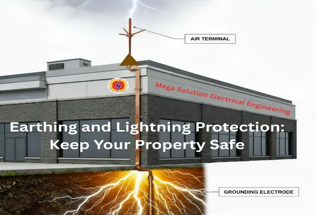
Direct strike protection requires physical interception of the lightning flash by an air termination system positioned above the protected structure. Without direct strike protection a lightning flash terminates on the structure itself causing structural damage and fire. The air termination system presents a preferred termination point that intercepts the flash before it reaches the protected structure.
Indirect strike protection requires surge protection devices at every point where electrical and telecommunications conductors enter the building. Additionally it requires adequate bonding and shielding within the building to limit induced voltages reaching sensitive equipment. Indirect strike effects cause equipment damage at distances far greater than direct strike effects. Furthermore they affect a much larger proportion of structures than direct strikes alone.
IEC 62305 and engineering best practice require both protection types in a complete earthing and lightning protection system. Installing only an external lightning protection system without internal surge protection leaves electronic equipment vulnerable to conducted and induced surges. Installing only surge protection without an external lightning protection system leaves the structure itself vulnerable to direct strike damage.
Lightning Risk Assessment
IEC 62305 Part 2 provides a structured methodology for calculating lightning risk to a structure. It determines whether lightning protection measures are necessary and to what protection level.
The risk assessment evaluates four risk components. These are the risk of loss of human life or permanent injury, loss of service to the public, loss of cultural heritage, and economic loss. Engineers calculate each risk component from factors including the local lightning flash density, structure dimensions and construction, type of occupancy and activity, consequences of a strike, and existing protection measures.
IEC 62305 risk assessments use the ground flash density Ng expressed in flashes per square kilometre per year. This value is distinct from the total lightning flash density which includes cloud to cloud flashes. The Ng value varies significantly across Ghana by region and season. Engineers performing risk assessments for Ghanaian structures should use current Ng data from the Ghana Meteorological Agency. Alternatively they can use published lightning flash density databases from Vaisala and the global lightning detection network. Relying on generalised regional estimates produces inaccurate risk assessments.
Engineers compare the calculated risk for each component against the tolerable risk threshold defined in IEC 62305. Where the calculated risk exceeds the tolerable threshold engineers must install lightning protection measures. They then determine the protection level necessary to reduce risk below the threshold. Structures in Ghana frequently require protection when engineers assess them using accurate local Ng data even if similar structures in lower flash density countries do not.
Lightning Protection System Components
A complete lightning protection system consists of external components that intercept and conduct lightning current safely to earth and internal components that prevent dangerous voltage differences and surge currents from reaching people and equipment within the protected structure.
Air Termination Systems
IEC 62305 Part 2 provides a structured methodology for calculating lightning risk to a structure. It determines whether lightning protection measures are necessary and to what protection level.
The risk assessment evaluates four risk components. These are the risk of loss of human life or permanent injury, loss of service to the public, loss of cultural heritage, and economic loss. Engineers calculate each risk component from factors including the local lightning flash density, structure dimensions and construction, type of occupancy and activity, consequences of a strike, and existing protection measures.
IEC 62305 risk assessments use the ground flash density Ng expressed in flashes per square kilometre per year. This value is distinct from the total lightning flash density which includes cloud to cloud flashes. The Ng value varies significantly across Ghana by region and season. Engineers performing risk assessments for Ghanaian structures should use current Ng data from the Ghana Meteorological Agency. Alternatively they can use published lightning flash density databases from Vaisala and the global lightning detection network. Relying on generalised regional estimates produces inaccurate risk assessments.
Engineers compare the calculated risk for each component against the tolerable risk threshold defined in IEC 62305. Where the calculated risk exceeds the tolerable threshold engineers must install lightning protection measures. They then determine the protection level necessary to reduce risk below the threshold. Structures in Ghana frequently require protection when engineers assess them using accurate local Ng data even if similar structures in lower flash density countries do not.
Down Conductors
Down conductors carry the lightning current from the air termination system to the earth termination system. Engineers and electricians route them as directly as possible from air termination to earth termination. They avoid sharp bends that increase conductor inductance and cause voltage differences between the down conductor and adjacent metallic structures.
IEC 62305 Part 3 Table 6 specifies minimum down conductor cross sectional areas. These are 16 square millimetres for copper conductors and 50 square millimetres for steel conductors. The number of down conductors required depends on the protection level and the perimeter of the structure. IEC 62305 Part 3 Table 4 specifies maximum spacing between down conductors as 10 metres for Lightning Protection Level I, 15 metres for Level II, 20 metres for Level III, and 25 metres for Level IV.
Engineers and electricians install test joints in each down conductor at approximately 0.5 metres above ground level. Test joints allow engineers to disconnect the down conductor from the earth termination for individual earth resistance measurement of each earth electrode. This disconnection does not disturb the complete system connection.
Engineers and electricians bond down conductors to metallic structural elements at regular intervals. This prevents dangerous side flash between the down conductor and adjacent metalwork during a lightning event. The intense magnetic field around a down conductor carrying peak lightning current induces voltage differences. These differences cause arcing to adjacent conductors unless bonding connections equalise the potential.
Earth Termination Systems
The earth termination system of a lightning protection installation dissipates the lightning current into the general mass of earth. Engineers design it to achieve a low earth resistance that limits ground potential rise during a lightning event. It must also withstand the high peak current of a lightning strike without mechanical damage.
IEC 62305 Part 3 specifies two types of earth termination. Type A arrangements use vertical rods or horizontal radial conductors connected individually to each down conductor. IEC 62305 recommends a minimum of two earth electrodes per down conductor. Type B arrangements use a ring conductor encircling the structure at a depth of at least 0.5 metres. Engineers supplement this with radial conductors or vertical rods where required to achieve the resistance target.
The target earth resistance for a lightning protection earth termination is below 10 ohms measured at low frequency. Where soil conditions make this difficult to achieve using conventional electrodes engineers apply chemical earth enhancement compounds to reduce soil resistivity in the immediate vicinity of the electrode. However chemical enhancement compounds must be compatible with the electrode material and must not cause corrosion or environmental contamination.
Surge Protection Devices
Surge protection devices, commonly abbreviated SPD, protect electrical and electronic equipment from transient overvoltages. Lightning strikes and switching operations generate these transient overvoltages. IEC standards and installation codes mandate SPDs at every point where electrical or telecommunications conductors enter the protected structure.
IEC 61643 classifies surge protection devices into three types based on their location in the installation and their energy handling capability.
SPD Types and Their Applications
Type 1 SPDs, also called Class I or Class B, protect at the origin of the installation where the supply enters the building. Engineers and electricians install them here to handle high energy surges from direct lightning strikes on or near the supply network. Type 1 SPDs use spark gap or combined spark gap and varistor technology to handle peak impulse currents of 25 to 100 kiloamperes.
Type 2 SPDs, also called Class II or Class C, go at distribution boards throughout the installation. Engineers and electricians install them to handle residual surge energy passing through the Type 1 SPD and protect the downstream distribution system. Type 2 SPDs typically use metal oxide varistor technology with peak impulse current ratings of 5 to 40 kiloamperes.
Type 3 SPDs, also called Class III or Class D, protect at the point of use adjacent to sensitive equipment. Engineers and electricians position them to handle low energy residual surges passing through Type 1 and Type 2 devices. They provide the final level of protection for computers, telecommunications equipment, medical devices, and other sensitive electronics. Type 3 SPDs have low voltage protection levels typically below 1,500 volts. This protects sensitive equipment that cannot tolerate higher transient voltages.
SPD Disconnectors and System Coordination
IEC 61643 requires that SPDs incorporate a disconnector. Alternatively engineers install a separate disconnector alongside the SPD. The disconnector isolates a failed SPD from the circuit without interrupting the protected supply. This prevents a failed SPD from causing a sustained short circuit that trips the upstream overcurrent protection. The disconnector may be integral to the SPD or may be a separate fuse or miniature circuit breaker. Either way it must match the SPD manufacturer’s specified requirements.
A coordinated three level SPD system uses all three SPD types together. Their combined energy absorption and voltage limiting capability provides comprehensive surge protection throughout the installation. Never install Type 2 or Type 3 SPDs without Type 1 SPDs at the installation origin. Doing so exposes downstream SPDs to energy levels exceeding their capability, causing SPD failure and leaving the installation unprotected.
Bonding and Isolation
Internal lightning protection measures prevent dangerous voltage differences between conductive parts within the protected structure during a lightning event. Two complementary approaches achieve this objective.
Lightning equipotential bonding connects all metallic services, structural metalwork, and equipment housings to the lightning protection earthing system. Engineers make these connections at the point of entry into the structure. This prevents dangerous potential differences between the lightning protection system and other metallic elements during a strike.
Isolation maintains physical separation between lightning protection conductors and other metallic elements where bonding is not practical. IEC 62305 specifies minimum separation distances between down conductors and other metalwork. These distances depend on the protection level and the length of the down conductor. Where engineers cannot maintain the required separation distance IEC 62305 requires bonding instead.
International Standards for Earthing and Lightning Protection
IEC 60364: Low Voltage Electrical Installations
IEC 60364 is the primary international standard for electrical installation design. It covers earthing requirements comprehensively across its multiple parts. Part 4-41 covers protection against electric shock. In addition, Part 5-54 covers earthing arrangements and protective conductors. Finally, Part 6 covers verification and testing requirements.
National standards bodies in most countries globally adopt IEC 60364 as the basis for their national electrical installation standards. These countries include most African nations, European countries, and many Asian and Pacific countries. Its earthing requirements define the minimum acceptable earthing system design for any compliant electrical installation.
IEC 62305: Protection Against Lightning
IEC 62305 is the primary international standard for lightning protection. Its four parts together cover the complete scope of lightning protection system design, installation, and maintenance.
Part 1 provides the general principles of lightning protection. Part 2 provides the risk management methodology for determining whether lightning protection is necessary and to what level. External lightning protection systems including air termination, down conductors, and earth termination fall under Part 3. Internal lightning protection measures including equipotential bonding, isolation, shielding, and surge protection devices fall under Part 4.
IEC 62305 defines four lightning protection levels abbreviated LPL I through LPL IV. LPL I provides the highest protection against the most severe lightning parameters. LPL IV provides minimum protection against less severe parameters. The risk assessment methodology of Part 2 determines the required protection level for any specific structure.
Ghana Standards Authority Requirements
The Ghana Standards Authority, commonly abbreviated GSA, adopts and publishes standards applicable to electrical installations and lightning protection in Ghana. The Ghana Wiring Regulations govern Ghana’s electrical installations. These regulations base their requirements on BS 7671 Requirements for Electrical Installations.
The Ghana Energy Commission Act 1997 Act 541 and its regulations establish the regulatory framework for electrical installations in Ghana. A competent person must certify every electrical installation against applicable standards before engineers energise and connect it to the public supply network.
For lightning protection specifically engineers must assess structures in Ghana under the IEC 62305 risk assessment methodology. Structures requiring protection must have lightning protection systems designed and installed in accordance with IEC 62305 or an equivalent accepted standard. High risk structures including hospitals, schools, telecommunications towers, and fuel storage facilities typically require mandatory lightning protection in Ghana.
BS 7671 and Its Global Influence
The Institution of Engineering and Technology published BS 7671 Requirements for Electrical Installations. It is one of the most widely adopted electrical installation standards globally. Countries including the United Kingdom, Ghana, and many others with historical connections to the British engineering tradition base their wiring regulations on it.
BS 7671 Part 4 covers protection for safety including protection against electric shock, thermal effects, and overcurrent. Part 5 covers selection and erection of equipment including earthing arrangements. Part 6 covers inspection and testing requirements. Engineers must satisfy these requirements and energise every new installation only after completing them.
The IET published the current 18th Edition in 2018. In 2022 the IET published Amendment 2 to the 18th Edition. This amendment contains significant changes to surge protection requirements in Part 4 and earthing requirements in Part 5. Installations in Ghana must comply with the 18th Edition including Amendment 2 and all subsequently published amendments.
Earthing and Lightning Protection for Specific Applications
Residential Installations
Residential earthing and lightning protection requirements follow the applicable national wiring regulations. In Ghana these regulations base their requirements on BS 7671. Every residential electrical installation must have a compliant earthing system. It must provide adequate fault current clearance for all protective devices and safe touch voltages on all exposed conductive parts.
TT is the most common residential earthing arrangement in Ghana. The supply network in many areas does not provide a metallic earth return, requiring a local earth electrode at the property. A driven rod electrode of 1.2 to 2.4 metres length provides adequate earth resistance in many Ghanaian soil conditions. However actual soil resistivity varies significantly across the country. Some locations require more extensive electrode systems to achieve compliant resistance values. Residual current devices are mandatory in TT systems where overcurrent devices alone cannot guarantee safe touch voltages.
Lightning protection for residential buildings is not universally mandatory under Ghanaian regulations. However engineers strongly recommend it for isolated properties, tall structures, and properties in areas of high lightning flash density. Properties with significant electronic equipment or valuable contents also benefit significantly. A risk assessment following IEC 62305 Part 2 methodology determines whether protection is necessary and to what level. Engineers should use accurate local Ng data from the Ghana Meteorological Agency for any specific residential structure assessment.
Commercial Buildings
Commercial buildings require more comprehensive earthing and lightning protection than residential properties. Their larger electrical installations, higher occupancy, more complex equipment, and greater economic consequences from lightning damage all justify this higher standard.
Main equipotential bonding in commercial buildings must connect all metallic services entering the building to the main earthing terminal. These services include water supply, gas supply, telecommunications cables, and any metallic structural elements. Engineers must connect main bonding conductors to the main earthing terminal before any branch connections. They size all bonding conductors in accordance with IEC 60364 Part 5-54 bonding conductor sizing tables.
Large commercial buildings with significant IT infrastructure and sensitive electronic equipment require a fully coordinated three level surge protection system. Engineers install this system at all electrical and telecommunications entry points. They must coordinate the surge protection system with the external lightning protection system. This ensures SPD energy ratings match the protection level the external system provides. Each SPD installation must include the correct disconnector specified by the SPD manufacturer. This prevents supply interruption from a failed device.
Industrial Facilities
Industrial earthing and lightning protection requires the most comprehensive approach of any application category. High fault current levels, high value equipment, hazardous process materials, and complex electromagnetic environments all combine to justify this requirement in industrial facilities.
Multiple earth electrodes interconnected in a ring or grid arrangement beneath the facility form the standard industrial earthing system. This arrangement achieves earth resistance values below 1 ohm for the complete installation. The earth grid provides both fault current clearance and step and touch voltage control for personnel working near electrical equipment.
Hazardous area installations require specific earthing and bonding arrangements. These arrangements prevent static electricity accumulation and sparking that could ignite flammable atmospheres. Engineers and electricians must bond all conductive equipment in hazardous areas to the installation earthing system. This requirement applies regardless of whether the equipment connects to the electrical supply. Tank farms, fuel storage areas, and chemical processing facilities require static earthing and bonding verification procedures. These procedures form part of their routine maintenance programme consistent with IEC 60079 hazardous area standards.
Generator Installations
Generator earthing requires specific attention. Generators introduce an additional earth fault current source into the installation. This source interacts with the utility supply earthing system in ways that create hazardous conditions if engineers do not design it correctly.
When a generator operates in parallel with the utility supply engineers must coordinate the earthing of both sources. This coordination prevents circulating earth currents and ensures earth fault protection operates correctly for faults regardless of which source supplies the load. The generator neutral earthing method, whether solidly earthed, resistance earthed, or isolated, must be compatible with the installation earthing system type and the protective devices used.
Standby generators operating in island mode establish their own earthing reference through the generator neutral earthing connection. A transfer switch disconnects them from the utility supply. The generator earthing electrode must achieve adequate earth resistance. Without it the generator’s protective devices cannot operate correctly for earth faults on the connected installation.
For comprehensive guidance on generator installation electrical systems including earthing requirements contact Mega Solution Electrical Engineering Ltd for generator installation and repair services across Ghana.
Telecommunications and Data Centre Installations
Telecommunications and data centre installations have the most demanding earthing requirements of any building type. The extreme sensitivity of the equipment to electromagnetic interference and transient voltages drives this requirement. The critical nature of the services they provide makes any compromise unacceptable.
Data centres typically require a dedicated earthing system separate from the general building earthing system. Engineers bond it to the general system at a single point to prevent circulating currents. The dedicated system achieves earth resistance below 1 ohm. Engineers also install a raised floor earth grid that provides a low impedance earth reference for all equipment within the raised floor environment.
Telecommunications earthing standards including ITU-T K.27 and ANSI TIA-607 specify detailed earthing and bonding requirements for telecommunications facilities. These requirements go beyond the general requirements of IEC 60364. These standards specify conductor sizing, connection methods, labelling requirements, and testing procedures specific to telecommunications environments.
Testing and Inspection of Earthing and Lightning Protection Systems
Earth Resistance Testing Procedures
Earth resistance testing verifies that the installed earthing system achieves the required resistance values. Engineers test against both the applicable standard and the specific installation design requirements. Engineers perform testing at installation commissioning and at the intervals specified in the applicable maintenance standard.
IEC 60364 Part 6 and BS 7430 Code of Practice for Earthing specify the three point fall of potential method as the standard technique for driven rod and plate electrodes. The earth resistance tester injects a test current between the electrode under test and a current auxiliary electrode. Engineers drive the current auxiliary electrode into the ground at a distance from the test electrode. A voltage auxiliary electrode measures the potential difference at an intermediate point between the two current electrodes. The tester calculates earth resistance from the ratio of the measured voltage to the injected current.
The correct positioning of the auxiliary electrodes is critical for accurate measurement. Engineers place the current auxiliary electrode at a distance sufficient to ensure the resistance zones of the two electrodes do not overlap. For a single driven rod electrode this distance is typically 5 to 10 times the rod length. Engineers place the voltage auxiliary electrode at 62% of the distance between the test and current electrodes for the most accurate measurement.
The stakeless clamp on method uses a clamp meter that encircles the earthing conductor. Engineers use it to measure earth resistance without driving auxiliary stakes. It suits installations where the earthing conductor forms a complete loop including the earth electrode, the installation earthing system, and the supply network earth. Engineers cannot use it to measure isolated earth electrodes. However it is practical for periodic verification testing of complete installation earthing systems.
Lightning Protection System Inspection
Lightning protection systems require visual inspection and continuity testing at defined intervals. IEC 62305 Part 3 and the applicable national standards specify these intervals. The inspection frequency depends on the protection level and the environment.
IEC 62305 specifies visual inspection every two years for Lightning Protection Level III and IV systems. Level I and II systems require visual inspection every year. IEC 62305 requires complete inspection including continuity and earth resistance testing every four years for LPL III and IV systems. LPL I and II systems require complete inspection every two years. IEC 62305 also requires additional inspection after any known lightning strike on or near the protected structure.
Importantly IEC 62305 also requires inspection after any modification to the protected structure that could affect lightning protection system performance. Building extensions, roof modifications, and new rooftop equipment must trigger a lightning protection system reassessment. Changes to metallic services and any other structural modification carry the same requirement. Engineers must confirm that the existing system continues to provide the required protection level for the modified structure.
Visual inspection covers all air termination components for mechanical damage, corrosion, and secure fixing. Engineers inspect down conductors along their complete length for mechanical damage, corrosion, and continuity of bonding connections to metallic structural elements. Engineers inspect test joints for correct assembly and freedom from corrosion. They inspect earth termination components where accessible for mechanical integrity and corrosion.
Continuity testing confirms that every component of the lightning protection system is electrically connected. The measured resistance must not significantly exceed the resistance of the conductor itself. High resistance connections indicate corroded joints, damaged conductors, or loose terminations that reduce the effectiveness of the lightning protection system.
Test Frequency and Documentation Requirements
Engineers must document all earthing and lightning protection tests in a test record. This record forms part of the installation’s permanent technical file. It must include the date of testing and the name and qualifications of the person performing the tests. It must also record the test equipment used including its calibration certificate reference, the test method applied, and the results for each measurement point.
Initial verification testing at installation commissioning produces the baseline test record. Engineers compare all subsequent periodic test results against this baseline. Deterioration in earth resistance values or continuity measurements between successive tests indicates developing problems. These problems require investigation and remedial action before the next scheduled test interval.
For installations where the earthing or lightning protection system is a regulatory or insurance requirement the test documentation provides compliance evidence. This evidence protects the property owner in the event of an insurance claim or regulatory inspection.
Common Earthing and Lightning Protection Faults
High Earth Resistance
High earth resistance is the most common earthing system fault. It is also one of the most consequential because it directly compromises the protective function of the earthing system for every circuit in the installation.
Several causes produce high earth resistance in practice. Soil drying during hot seasons reduces moisture content and therefore soil conductivity. Corrosion of the earth electrode reduces its effective surface area. Mechanical damage to the earthing conductor between the main earthing terminal and the earth electrode interrupts the earth connection. Inadequate initial electrode design that did not account for actual soil resistivity at the installation location produces consistently high resistance from the outset.
Several remedial measures address high earth resistance effectively. Driving additional electrodes in parallel with the existing electrode reduces the combined resistance. Installing chemical earth enhancement compounds around the existing electrode lowers soil resistivity in the immediate vicinity. Replacing a corroded electrode with a new corrosion resistant electrode restores the original design resistance. Installing a deep driven electrode that reaches lower soil layers with higher moisture content achieves lower resistivity where surface soil conditions are poor.
Corroded or Damaged Earthing Connections
Earthing connections are subject to corrosion from soil chemistry, atmospheric exposure, and galvanic action between dissimilar metals. A corroded connection may appear sound during visual inspection. However it can have significantly higher resistance than a clean connection, compromising the effectiveness of the earthing system.
Connections between copper earthing conductors and galvanised steel structural elements are particularly vulnerable to galvanic corrosion. The electrolytic action between copper and zinc in the presence of moisture accelerates corrosion of both materials at the junction. Using compatible metals for earthing connections or applying protective compound to dissimilar metal junctions prevents this galvanic corrosion.
Regular inspection and testing identifies corroded connections before they cause complete failure of the earthing system. Engineers must clean connections showing visible corrosion or high resistance back to bright metal. They then remake them with the correct materials and connection method.
Inadequate Bonding
Inadequate bonding connections are a common finding during electrical installation inspection. They appear particularly in older installations that predate current bonding requirements. They also appear in installations that property owners or contractors modified without maintaining bonding integrity.
Electricians frequently omit or incorrectly install gas pipe bonding in residential and commercial properties. Plastic gas pipes and plastic pipe inserts at meter connections interrupt the metallic continuity of the gas installation. This requires bonding connections on the installation side of any plastic section. Electricians who do not understand this requirement sometimes omit bonding because the gas pipe appears not to be metallic at the point of connection.
Contractors sometimes omit supplementary bonding in bathrooms and shower rooms from new installations. It is also frequently missing in older properties where current bonding requirements did not apply at the time of installation. The consequences are particularly serious in wet locations. Reduced body resistance and increased earth contact from wet conditions make missing bathroom bonding a genuine life safety risk.
Failed or Missing Surge Protection Devices
Surge protection devices have a finite energy absorption capacity that depletes progressively with each surge event they handle. An SPD that has absorbed its rated energy capacity provides no further protection against subsequent surges. Furthermore it may not give any visible indication of failure.
Most quality surge protection devices incorporate a visual status indicator. This indicator changes colour or displays a warning symbol when the device has reached the end of its useful service life. Engineers must check these indicators during every routine inspection. An SPD showing a fault indication must be replaced immediately to restore surge protection capability. The replacement SPD must include a correctly rated disconnector as specified by the manufacturer.
Engineers frequently find missing surge protection devices at points of entry in commercial and industrial installations. Many of these installations were built before surge protection requirements became mandatory in national standards. Retrofitting SPDs to existing installations provides immediate improvement in equipment protection. It also reduces the risk of lightning related equipment damage and data loss.
Earthing and Lightning Protection Services From Mega Solution Electrical Engineering
Mega Solution Electrical Engineering provides comprehensive earthing and lightning protection services for residential, commercial, and industrial clients across Ghana. Our services cover the complete scope from initial risk assessment and system design through to installation, testing, certification, and ongoing maintenance.
Our Earthing and Lightning Protection Capabilities
Mega Solution Electrical earthing installation services include earth electrode design and installation. We select driven rods, horizontal conductors, ring electrodes, and foundation electrodes based on the specific soil conditions and resistance requirements of each installation. Also, we size all earthing conductors and bonding connections in accordance with IEC 60364 and BS 7671 18th Edition including Amendment 2. We test all installations using calibrated earth resistance testing equipment before issuing the installation certificate.
Our lightning protection services cover complete external lightning protection system design and installation. Mega Solution engineers design and install air termination systems, down conductors, earth termination systems, and test joints to IEC 62305 requirements. We perform lightning risk assessments following IEC 62305 Part 2 methodology. Our engineers use current Ng data from the Ghana Meteorological Agency to determine the required protection level. This ensures every installed system is correctly specified for the actual lightning risk at each location.
Our surge protection services install coordinated three level SPD systems at electrical and telecommunications entry points in commercial and industrial buildings. Mega Solution engineers verify all SPD ratings and coordination against the external lightning protection level before installation. Every SPD installation includes the correctly rated disconnector device specified by the manufacturer. We specify and install SPDs from proven manufacturers with published test certification to IEC 61643 requirements.
Testing, Inspection, and Ongoing Maintenance
Our testing and inspection services provide periodic verification of existing earthing and lightning protection systems. We use calibrated test equipment and produce detailed test reports documenting the condition of every system component. Our reports identify any deterioration or deficiency requiring remedial action. We also perform post modification inspections whenever structural changes affect the performance of existing lightning protection systems.
Mega Solution Electrical Engineering installs and maintains earthing and lightning protection systems that protect the people, equipment, and operations your property supports. Contact Mega Solution Electrical Engineering today to discuss earthing and lightning protection services for your residential, commercial, or industrial installation across Ghana.
Remote Monitoring System Integration and Configuration
Integrating a generator control module with a remote monitoring system requires configuring the communication interface on the control module, establishing the network connection between the control module and the monitoring platform, and mapping the control module data registers to the monitoring system’s data model.
Configure communication parameters on the control module including protocol selection, baud rate for serial connections, IP address for ethernet connections, and device address for multi-device installations. These parameters must match exactly between the control module and the monitoring system. A single incorrect parameter prevents communication entirely.
Establish network security for remote monitoring connections. Generator control systems connected to corporate networks or the internet are potential cybersecurity targets. Implement network segmentation that isolates the generator control network from general corporate network traffic. Use encrypted communication protocols where available. Implement access controls that limit remote command capability to authorised personnel.
Configure alarm notification routing to ensure that critical alarms reach the appropriate personnel immediately. A high coolant temperature alarm at 3am must reach the on-call engineer within minutes to allow intervention before the high temperature shutdown occurs and the facility loses power. Configure alarm escalation that notifies additional personnel if the primary contact does not acknowledge the alarm within a defined period.
Using Remote Monitoring Data for Maintenance Planning
Remote monitoring data transforms industrial generator maintenance planning from interval based scheduling to condition based scheduling. Instead of performing maintenance at fixed calendar or hour intervals regardless of actual equipment condition, condition based maintenance uses monitoring data to identify when maintenance is actually required.
Trend analysis of coolant temperature data identifies developing cooling system problems before they cause overheating. A coolant temperature that has increased by 5 degrees Celsius over three months of monitoring at constant load indicates a developing cooling efficiency reduction from radiator blockage, coolant degradation, or thermostat drift. Maintenance intervention at this early stage costs a fraction of the repair required after an overheating event.
Fuel consumption trend analysis identifies developing engine efficiency problems. An engine consuming 5% more fuel per hour at equivalent load than it did three months previously indicates developing problems including injector wear, air filter restriction, or turbocharger efficiency reduction. Each of these causes fuel consumption increase before it causes measurable power loss.
Battery voltage trend analysis identifies batteries approaching the end of their service life before they cause starting failures. A float charged battery whose resting voltage has declined from 12.7 to 12.3 volts over six months of monitoring indicates sulphation progressing to the point where replacement should be planned before the next extended outage period.
Mega Solution Electrical Engineering Ltd designs, installs, and maintains remote monitoring systems for industrial generator installations across Ghana, providing facility managers and plant engineers with continuous visibility of generator health and performance through web-based and mobile monitoring platforms.
Industrial Generator Maintenance Services From Mega Solution Electrical Engineering
Mega Solution Electrical Advanced Technical Capabilities
Mega Solution Electrical Engineering provides the complete range of advanced industrial generator maintenance services required by critical facilities across Ghana and internationally.
The full range of advanced industrial generator maintenance services sits within our technical capabilities. Vibration analysis uses calibrated accelerometer equipment and specialist analysis software. Thermal imaging surveys use calibrated infrared cameras with full thermographic reporting. Insulation resistance testing and polarisation index assessment cover generator windings comprehensively. Precision shaft alignment uses laser alignment equipment and includes alignment certificate documentation. Automatic mains failure systems receive commissioning, testing, and ongoing maintenance to manufacturer specifications. Generator paralleling systems including synchronisation procedure verification and load sharing optimisation form part of our core design and maintenance offering. Remote monitoring systems are designed, installed, configured, and integrated with building management and SCADA systems by our engineers.
Our engineers hold relevant professional qualifications in electrical engineering. They bring practical experience with the full range of generator control systems, paralleling systems, and monitoring platforms. This experience covers industrial installations in Ghana and internationally.
Industrial Generator Maintenance Programmes
Mega Solution Electrical Engineering designs industrial generator maintenance programmes around the specific requirements of each installation rather than applying a generic schedule to all clients. Programme design considers the criticality of the installation, the regulatory and insurance compliance requirements applicable to the facility, the age and condition of the generator assets, the operating profile including running hours and load profile, and the client’s internal maintenance capability.
Industrial generator maintenance programmes from Mega Solution include monthly condition monitoring visits covering vibration measurement, thermal imaging of electrical connections, battery testing, and operational parameter review. Quarterly intermediate services covering oil and filter changes, fuel system inspection, cooling system assessment, and control system testing. Annual major services covering full mechanical overhaul, alternator insulation resistance testing, shaft alignment verification, AMF system functional testing, and load bank testing at rated capacity.
All maintenance activities are documented in detailed service reports that provide the complete maintenance record required for regulatory compliance, insurance purposes, and manufacturer warranty support.
Contact Mega Solution for Industrial Generator Services
Mega Solution Electrical Engineering maintains industrial generators to the standards described in this guide. This ensures your generator installation performs its critical function reliably every time your facility needs it. Our advanced diagnostic technology, professional engineering expertise, and systematic maintenance disciplines deliver the reliability that critical industrial operations demand.
Contact Mega Solution Electrical Engineering today to discuss an industrial generator maintenance programme tailored to your specific installation, operational requirements, and compliance obligations. Our engineering team will assess your current installation condition, identify any immediate concerns, and design a maintenance programme that eliminates unplanned generator failure from your operational risk profile.
Always Hire Professional Generator Experts
No matter urgent any electrical repairs seem, it’s never okay to attempt to handle them on your own. Trying to take care of electrical problems without professional training is extremely dangerous. If you or someone else aren’t hurt during your attempt, there’s still a chance that you’ve left something undone that poses a huge risk to you, your home, or your family. Always engage mega solution electrical engineering the professional generator experts for your generator installation, repairs and maintenance services. Visit Our Google Business Profile
Mega Solution Electrical Engineering – Generator Experts In Ghana for your generator Repairs and Maintenance
Our generator expert in Ghana technicians for your generator repairs and maintenance know what a hassle any generator problems can be, which is why we’ll always respond to any requests for service as quickly as possible. And because all of our technicians are licensed, background checked, and professionally trained, you’re guaranteed to receive the best quality service and workmanship available when you call Mega Solution Electrical Engineering the generator experts in Ghana. We can assist with all your electrical needs including:
- Generator Installation and Repair Services
- Best Industrial Electrical Automation services
- Best Electric Motor Rewinding Services
- Earthing Installations and Upgrades Services
- Electro-Mechanical services
- Lighting Installation
- Residential Electrical Installation Services
- Electrical Panel Replacement
- LED Lighting
- Industrial electrical Installation Services
- Electrical Troubleshooting and Repairs
- Professional Electrical Support and Training Services
- Electrical Wiring Design and Engineering Services
- Electrical Energy and Power Auditing Services
- Distribution Panels Fabrication and Upgrades Services
- Professional electrical contractors in Ghana
- Commercial electrical Installation Services
- Licensed Electricians in Ghana
- Home Wiring
- Consulting and Advisory services
- Electrical Wirings Testing and Inspection Services
- Wiring Replacement and Upgrade Services
- Residencial, commercial and Industrial wiring Services
When searching for a reliable electrician, call us at +233 24 415 1232 We specialize in electrical repairs, indoor and outdoor lighting installations, panel upgrades, and even hot tub wiring!

Mega Solution Electrical Engineering Ltd
Mega Solution Electrical Engineering Ltd, a licensed and certified electrical engineering company in Ghana specializing in electrical contracting, generator maintenance, energy audits, and industrial electrical services.
Search
Electrical Wiring Contract – What Can Go Wrong or Right
Generator Service Experts in Ghana, When the Lights Go Out – Mega Solution Electrical to the Rescue!
Categories
- Certified Electricians Ghana
- Earthing Installations
- Earthing Maintenance
- Electrical Consulting
- Electrical Contractors
- Electrical Installation Ghana
- Electrical Maintenance Ghana
- Electrical Repair Ghana
- Electrical Safety
- Electrical Training
- Energy Auditing
- Engineering Services
- Generator Installation
- Generator Maintenance Ghana
- Generator Repair
- Generator Services
- Generator Servicing Ghana
- Ghana Electrical Licensing
- Ghana Electrical Services
- Installation Services
- Licensed Electricians
- Motor Rewinding
- Residential Electrical Service
Archive
| M | T | W | T | F | S | S |
|---|---|---|---|---|---|---|
| 1 | 2 | 3 | 4 | |||
| 5 | 6 | 7 | 8 | 9 | 10 | 11 |
| 12 | 13 | 14 | 15 | 16 | 17 | 18 |
| 19 | 20 | 21 | 22 | 23 | 24 | 25 |
| 26 | 27 | 28 | 29 | 30 | 31 | |
Tags
- Agricultural Engineering
- Cable Sizing
- Commercial Electrical Contracting
- Earthing Installations and Upgrades Services
- Earthing Systems
- Earthing System Upgrades
- Electrical Advisory Service
- Electrical Company
- Electrical Contractors in Ghana
- Electrical Design Ghana
- Electrical Energy and Power Auditing Services
- Electrical Energy Auditing
- Electrical Load Calculation
- Electrical Panel Upgrades
- Electrical Repair Services
- Electrical Safety Training Ghana
- Electrical Services Ghana
- Electrical Training Services Ghana
- Electrical Troubleshooting
- Electrical Wiring Certificate Ghana
- Electrical Wiring Design and Engineering Services
- Electrical Wiring Design Ghana
- Electrical Wiring Installation
- Electrical Wiring Upgrades
- Electrical Workshop Training
- Electricians
- Electricians in Ghana
- Engineering Services Ghana
- Generator experts in Ghana
- Generator Installation and Repair Services
- Generator Maintenance Contracts
- Generator Maintenance Ghana
- Generator Repair Services
- Industrial Electrical Wiring
- Industrial Generator Maintenance
- Industrial generator repair services
- Licensed Electrical Contractors Ghana
- Licensed Electricians in Ghana
- Lightning Protection Systems
- Power Auditing Services
- Professional Electrical Support
- Residential Electrical Installation Ghana
- Three Phase Power
- Voltage Drop
- Workplace Electrical Safety
Prayer Warfare
Recent Comments
